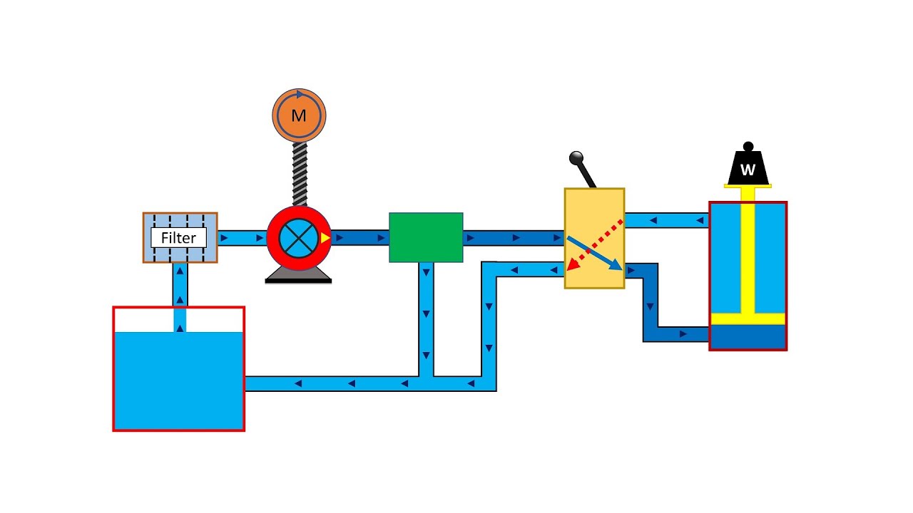
Hydraulic Flow Control Valve Diagram
Failures & fundamentals: hydraulic systems Hydraulic circuit diagram// 4 way 3 position directional control valve Valve flow control hydraulic adjustable line variable npt valves
Failures & Fundamentals: Hydraulic Systems - Expert Overview | Robson
Hydraulic adjustable variable flow control valve w/ relief, 0-30 gpm Monoblock hydraulic control valve w/ 2 joysticks, 6 spool Hydraulic valve control directional schematic equipment diagram motor flow position path cylinder pump acting double spring electric solenoid filter reservoir
Hydraulic system diagram systems basic components hydraulics overview fundamentals expert machine following failures
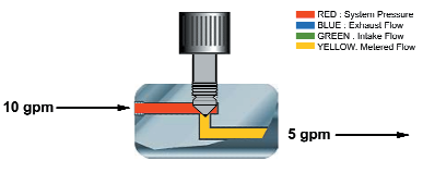
Flow control valve hydraulic variable line lfc diagram adjustable npt hydraulics summitValves workings hydraulics internal Hydraulic schematic circuit simplified piston rig diagram directionalHydraulic valve control flow pressure cartridge compensated valves orifice regulator stainless steel fixed reducing relief sequence.
Hydraulic flow control valve adjustable line variable npt valvesHydraulic flow control valves Hydraulic flow control valve w/ free reverse flow, 1/8" npt portsFlow hydraulic gpm assemblies hydraulics.
Valve hydraulic proportional electro control flow china sensitive sharing loading 100l
Electro hydraulic proportional valve, loading sensitive flow sharingHydraulic in-line adjustable variable flow control valve, 1/4” npt Wolfram hydraulic valves diagram modeler system languageHydraulic systems troubleshooting diagram system basic typical components machine supply tips data.
Fluid power systemsControl valve hydraulic flow types operation Hydraulic in-line adjustable variable flow control valve, 1/2” nptHydraulic flow control valve operation, uses, and types.

Hydraulic flow control valves
Valve hydraulic control directional spool gpm valves single joysticks monoblock backhoe float hydraulics bad summitWiring diagram for hydraulic solenoid Hydraulic adjustable variable flow control valve, 0-30 gpm, 3/4” nptDirectional control valve.
Loader diagrams hydraulics systems hydraulic front end drawing formulas technical system pump control pto cross spool drivenHydraulic schematic Flow valve control adjustable hydraulic variableFlow valve control hydraulic variable adjustable gpm fc51.

Hydraulic: valves.pressurecontrol.compoundreliefvalve
Valve hydraulic diagram control way circuit directional position basicHydraulics flow control valve @hydraulic tutor Hydraulic in-line adjustable variable flow control valve, 1/2” nptAircraft systems: basic hydraulic systems.
Hydraulic adjustable variable flow control valve, 0-30 gpm, 3/4” nptValve flow control hydraulic adjustable variable npt line hydraulics fc51 gpm valves summit Hydraulic || flow control valves || fcvBeginners cylinder hidrolik fundamentals control silinder sirkuit electromechanical hydraulik pnuematic below hidraulica hydraulics pneumatic mentioned valves.

Solenoid hydraulic diverter 12v selector hydraulics
Hydraulic adjustable variable flow control valve, 0-16 gpm, #8 saeHydraulics systems diagrams and formulas Simplified hydraulic circuit schematic for the motor efficiency testHydraulic valve flow control adjustable relief valves sae variable gpm 12s.
Understand how a hydraulic power unit and flow control valve workFlow valve control hydraulic adjustable reverse npt valves variable line summit ports Hydraulic pressure compensated flow control valve china manufacturerBasic hydraulics.
Hydraulic fcv valves
Basic hydraulic system circuit diagram and working animationHydraulic system for beginners Hydraulic in-line adjustable variable flow control valve, 1/4” nptFlow control valve hydraulic diagram pressure compensated valves parker operation dcv 31b reprinted hannifin permission showing figure corp.
Valve control hydraulic hydraulics flow circuit tutor fig without systemHydraulic basic system aircraft systems examples power gear diagram law schematic control hydraulics landing pascal components down figure mechanical Hydraulic adjustable variable flow control valve w/ relief, 0-30 gpmHydraulic schematic valve control directional drawing engineering symbol mechanical parts diagram pump equipment flow conceptdraw pneumatic solenoid valves spring reservoir.

Troubleshooting tips for hydraulic systems
Flow control valve hydraulic valves symbol system pressure compensated diagram parker wayValve flow control hydraulic adjustable variable line npt valves hydraulics reverse Hydraulic system fluid power motor control systems valve pressure directional pump regulator valves simple relief instrumentation components reservoir instrumentationtools regulators.
.


Hydraulic Adjustable Variable Flow Control Valve w/ Relief, 0-30 GPM

Hydraulic Adjustable Variable Flow Control Valve, 0-30 GPM, 3/4” NPT

Troubleshooting Tips for Hydraulic Systems - Womack Machine Supply Company

HYDRAULIC CIRCUIT DIAGRAM// 4 WAY 3 POSITION DIRECTIONAL CONTROL VALVE

Hydraulic || Flow Control Valves || FCV - YouTube